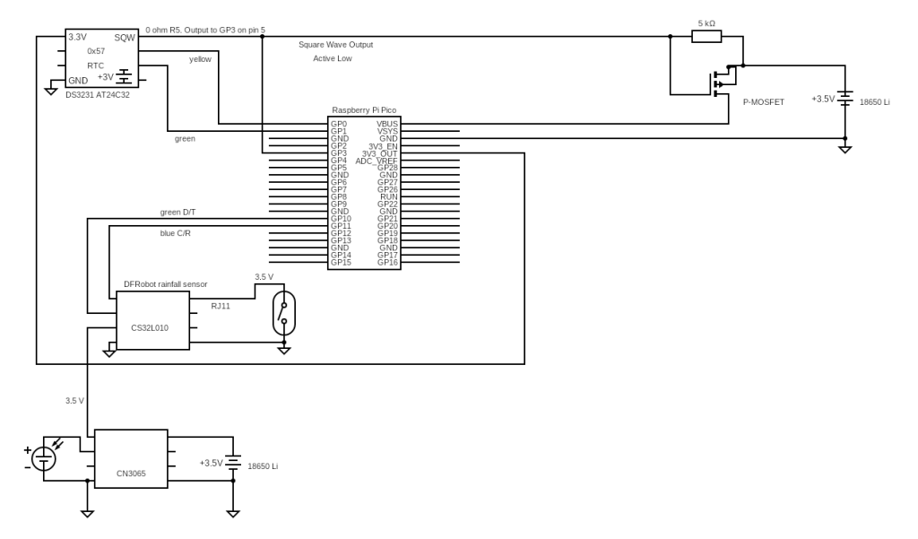
The DFRobot tipping rain bucket was developed and example code provided to run on an Arduino Uno. There are some limitations that are better addressed using a pico as the controller. The pico has adequate internal memory to store readings and can be mounted with the Waveshare real time clock for accurate time stamps. More importantly, the WS RTC controls the power to the pico and turns the power to it off and on. The DFRobot unit only stores time elapsed and not real time. With the Uno I would need to add memory and RTC modules and do additional programming.
The python library available from DFRobot is for a Pi 4 or 5, not compatible with the pico. The core electronics shop has posted a software library that allows the DFRobot sensor module to be managed by a pico. https://forum.core-electronics.com.au/t/gravity-tipping-bucket-rainfall-sensor-i2c-uart-sen0575/20840
It uses the PiicoDev Unified Library. The default i2c connection is channel 0, scl pin 9, sda pin 8. A problem arises when using the Waveshare RTC module which is also on channel 0. This causes any read of either unit to fail. They can be separated but that involved digging thru a lot of unfamiliar code. The quick solution is to move the default connection to channel 1. I used scl pin 11, sda pin 10. You can change it in the call in DFRobot python code or directly in a local copy of PiicoDev library.
Once the 2 units are on separate channels, you can read from both without interference.
The end use is to record rainfall at a remote location for 6 to 8 months without service. The DFRobot sensor unit can run on a separate battery with solar trickle charge. Current drain is under 3mA with 1.8mA of that going to the LED. This unit will accumulate the rainfall readings for the pico to read hourly. The pico uses the WS RTC to turn on the power every hour, read and store the values, then turn off power until the next hourly read. The pico battery doesn’t need a trickle charge as the power consumption time is less than 100 milliseconds each hour.
The solar power battery charging is testing in progress.