Using DFRobot tipping rain bucket with Raspberry Pico and Waveshare real time clock

The DFRobot tipping rain bucket was developed and example code provided to run on an Arduino Uno. There are some limitations that are better addressed using a pico as the controller. The pico has adequate internal memory to store readings and can be mounted with the Waveshare real time clock for accurate time stamps. More importantly, the WS RTC controls the power to the pico and turns the power to it off and on. The DFRobot unit only stores time elapsed and not real time. With the Uno I would need to add memory and RTC modules and do additional programming.

The python library available from DFRobot is for a Pi 4 or 5, not compatible with the pico. The core electronics shop has posted a software library that allows the DFRobot sensor module to be managed by a pico. https://forum.core-electronics.com.au/t/gravity-tipping-bucket-rainfall-sensor-i2c-uart-sen0575/20840

It uses the PiicoDev Unified Library. The default i2c connection is channel 0, scl pin 9, sda pin 8. A problem arises when using the Waveshare RTC module which is also on channel 0. This causes any read of either unit to fail. They can be separated but that involved digging thru a lot of unfamiliar code. The quick solution is to move the default connection to channel 1. I used scl pin 11, sda pin 10. You can change it in the call in DFRobot python code or directly in a local copy of PiicoDev library.

Once the 2 units are on separate channels, you can read from both without interference.

The end use is to record rainfall at a remote location for 6 to 8 months without service. The DFRobot sensor unit can run on a separate battery with solar trickle charge. Current drain is under 3mA. This will accumulate the rainfall readings for the pico to read hourly. The pico uses the WS RTC to turn on the power every hour, read and store the values, then turn off power until the next hourly read. The pico battery doesn’t need a trickle charge as the power consumption is for less than 100 milliseconds each hour.
Adding a microSD card adapter to a raspberry pi pico

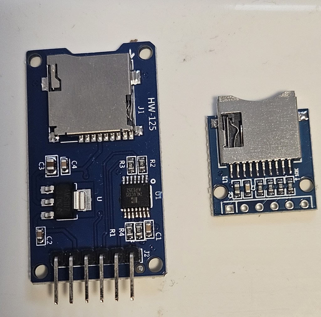
There are 2 basic types of adapters on the market: the WH-125 and the Adafruit. Both use the same micropython driver and have the same pins for connections as an SPI peripheral. They can also be mounted and used in circuitpython using the Adafruit libraries. They are directly interchangeable in software but you have to be extremely careful when making the physical connections otherwise you get “no SD card” or other errors that can be puzzling.

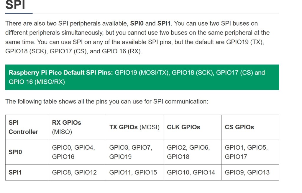
It may be necessary to physically move some of the pin connections when you need to add additional peripherals e.g. external temperature probe. When making changes to pin layout, keep track of which pins are associated with each function on SPI bus you are using. SPI0 and SPI1 pins do not overlap. MISO, MOSI, clock and select are limited to specific GPIO pins in each bus.

A great resource is https://randomnerdtutorials.com/raspberry-pi-pico-w-pinout-gpios/#spi

I had to resort to switching between 2 breadboards connected to Thonny so I could test the adapters separately and efficiently. There are multiple examples of programs for testing and using the microSD card adapter. They work but are not all the same code. There may be an example that is easier to understand and adapt to your specific needs.

The sdcard.py driver is found at https://github.com/micropython/micropython-lib/tree/master/micropython/drivers/storage/sdcard

Example test code:
Circuitpython: https://github.com/printnplay/Pico-CircuityPython/blob/main/SDCartTest.py
Micropython: https://randomnerdtutorials.com/raspberry-pi-pico-microsd-card-micropython/#datalogging
Micropython: https://core-electronics.com.au/guides/makerverse-micro-sd-adapter-micropython-guide/#modules

DS3231 Real Time Clock. How to set the alarm

This is in combination with the Raspberry Pi Pico. Use the chip to keep time while the Pico is in deep sleep or powered off. I need to trigger a thyristor, wake up the Pico, make & store a measurement then power off again.

The timer chip is the core of a number of products from a variety of makers. However, when it comes to setting an alarm, there is remarkably little information for the average user. Here is the function; here are the 8 variables. No meaningful examples or explanation. Fortunately, there are enough software versions that I was able to look at the source code and figure out what settings are needed to get the alarm to work.

This code is from https://RandomNerdTutorials.com/raspberry-pi-pico-ds3231-rtc-micropython/
Alarm times (year, month, day, weekday, hour, minute, second, millisecond)
alarm_time = urtc.datetime_tuple(2025, 04, 09, None, 21, 12, 00, 0)
Sets the alarm time for Apr 9, 2025 at 9:12PM.

However if you want to set the alarm to trigger every second, this is what you need.
alarm_time = urtc.datetime_tuple(None, None, None, None, None, None, None, 0
This outputs an alarm every time the millisecond counter reaches zero. That is every second.
To trigger every minute, set the seconds to 0 and milliseconds to None.

Couple of notes on hardware/software

The Waveshare chip needs to have a jumper installed to get the signal to the output pin. However, the physical layout and tiny size make it very difficult to actually solder anything into place.

There are drivers from an assortment of vendors based on the Hinch github repository. They use the same name for driver file but the driver is specific to the board. That can cause a lot of confusion when you run the software and it errors out. I had to put remarks in the header of all files as to source and which chip it runs on.

If you change the driver, unplug the Pico and allow it to clear. Prior drivers can leave settings that cause the new driver to fail.

Pi pico not recognized after updating micropython firmware

Short answer: a bug in the latest version of Micropython for Raspberry Pi pico. Recover by installing an older version.

Update. The latest version of Micropython does not cause this problem. Seems to be limited to this single version.

I bought a batch of Raspberry pi picos in Nov 2021. Been working with 2 of them ever since with no problem. Decided to update the micropython firmware. The units then lost connection to the computer with no COM port available. They will now mount in boot mode and Thonny will download the file to the pico but then fails with a message that a com port cannot be found. Tested with both Windows 11 Thonny, Raspberry Pi Thonny and manual drag/drop. Neither computer can find a pico com port. Tried 2 other unused picos in the same batch and had the same problem from the start. Tried using zadig to install a new USB driver on the units; no success but a new error message: “Device Descriptor Request Failed”

Decided it was probably a bug in the 1.24.0 version of micropython. Found the compiled archives of past versions and installed 1.23.0 by drag and drop. This version installed correctly and had communication with Thonny thru the USB connection. When doing an internet search for compiled past versions, Google will take you to github mostly where you can compile the version you want. The archive you actually want is on the micropython site here.