Adding a microSD card adapter to a raspberry pi pico

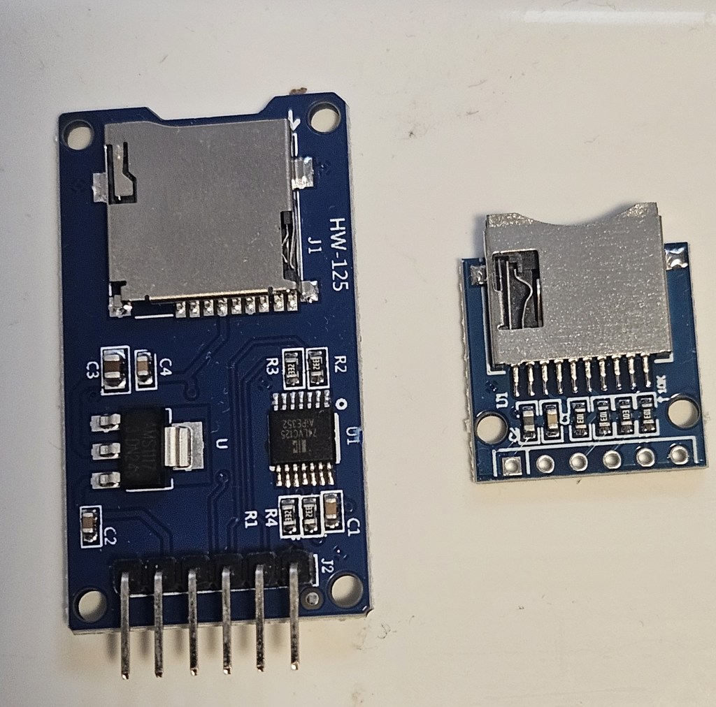
There are 2 basic types of adapters on the market: the WH-125 and the Adafruit. Both use the same micropython driver and have the same pins for connections as an SPI peripheral. They can also be mounted and used in circuitpython using the Adafruit libraries. They are directly interchangeable in software but you have to be extremely careful when making the physical connections otherwise you get “no SD card” or other errors that can be puzzling.

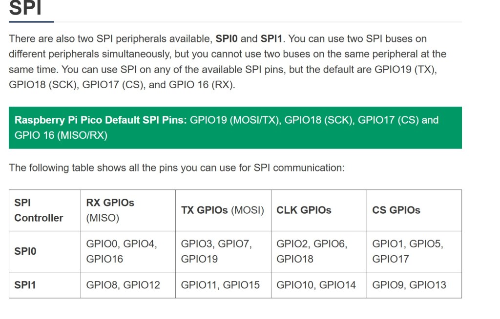
It may be necessary to physically move some of the pin connections when you need to add additional peripherals e.g. external temperature probe. When making changes to pin layout, keep track of which pins are associated with each function on SPI bus you are using. SPI0 and SPI1 pins do not overlap. MISO, MOSI, clock and select are limited to specific GPIO pins in each bus.

A great resource is https://randomnerdtutorials.com/raspberry-pi-pico-w-pinout-gpios/#spi

I had to resort to switching between 2 breadboards connected to Thonny so I could test the adapters separately and efficiently. There are multiple examples of programs for testing and using the microSD card adapter. They work but are not all the same code. There may be an example that is easier to understand and adapt to your specific needs.

The sdcard.py driver is found at https://github.com/micropython/micropython-lib/tree/master/micropython/drivers/storage/sdcard

Example test code:
Circuitpython: https://github.com/printnplay/Pico-CircuityPython/blob/main/SDCartTest.py
Micropython: https://randomnerdtutorials.com/raspberry-pi-pico-microsd-card-micropython/#datalogging
Micropython: https://core-electronics.com.au/guides/makerverse-micro-sd-adapter-micropython-guide/#modules

DS3231 Real Time Clock. How to set the alarm

This is in combination with the Raspberry Pi Pico. Use the chip to keep time while the Pico is in deep sleep or powered off. I need to trigger a thyristor, wake up the Pico, make & store a measurement then power off again.

The timer chip is the core of a number of products from a variety of makers. However, when it comes to setting an alarm, there is remarkably little information for the average user. Here is the function; here are the 8 variables. No meaningful examples or explanation. Fortunately, there are enough software versions that I was able to look at the source code and figure out what settings are needed to get the alarm to work.

This code is from https://RandomNerdTutorials.com/raspberry-pi-pico-ds3231-rtc-micropython/
Alarm times (year, month, day, weekday, hour, minute, second, millisecond)
alarm_time = urtc.datetime_tuple(2025, 04, 09, None, 21, 12, 00, 0)
Sets the alarm time for Apr 9, 2025 at 9:12PM.

However if you want to set the alarm to trigger every second, this is what you need.
alarm_time = urtc.datetime_tuple(None, None, None, None, None, None, None, 0
This outputs an alarm every time the millisecond counter reaches zero. That is every second.
To trigger every minute, set the seconds to 0 and milliseconds to None.

Couple of notes on hardware/software

The Waveshare chip needs to have a jumper installed to get the signal to the output pin. However, the physical layout and tiny size make it very difficult to actually solder anything into place. I haven’t managed to do it yet. Gave up and switched to the DS3231 AT24C32 module.

There are drivers from an assortment of vendors based on the Hinch github repository. They use the same name for driver file but the driver is specific to the board. That can cause a lot of confusion when you run the software and it errors out. I had to put remarks in the header of all files as to source and which chip it runs on.

If you change the driver, unplug the Pico and allow it to clear. Prior drivers can leave settings that cause the new driver to fail.

Pi pico not recognized after updating micropython firmware

Short answer: a bug in the latest version of Micropython for Raspberry Pi pico. Recover by installing an older version.

Update. The latest version of Micropython does not cause this problem. Seems to be limited to this single version.

I bought a batch of Raspberry pi picos in Nov 2021. Been working with 2 of them ever since with no problem. Decided to update the micropython firmware. The units then lost connection to the computer with no COM port available. They will now mount in boot mode and Thonny will download the file to the pico but then fails with a message that a com port cannot be found. Tested with both Windows 11 Thonny, Raspberry Pi Thonny and manual drag/drop. Neither computer can find a pico com port. Tried 2 other unused picos in the same batch and had the same problem from the start. Tried using zadig to install a new USB driver on the units; no success but a new error message: “Device Descriptor Request Failed”

Decided it was probably a bug in the 1.24.0 version of micropython. Found the compiled archives of past versions and installed 1.23.0 by drag and drop. This version installed correctly and had communication with Thonny thru the USB connection. When doing an internet search for compiled past versions, Google will take you to github mostly where you can compile the version you want. The archive you actually want is on the micropython site here.

Raspberry pi pico: Saving data to local memory

The pico has 2MB of local memory that can be used for data and program storage. One online resource states the maximum file size is 128KB and going over that corrupts the file; however, I have recorded 481KB files successfully. The files are accessible in the Thonny editor and can be copied to the local computer. Developing this for hourly recording of a remote stream to know high it rises after storms. Sleep for an hour, wake up, record a measurement and go back to sleep for another hour. Come back a month later to collect data.

Commands
gage_data = open(“gage_height”,”w”) #create file for writing or “a” for appending. Append will create the file if is not already there
gage_data.write(“height”) #writes data to file buffer. Does not write to memory yet. If it’s not a clean shutdown, the buffer is lost.
gage_data.flush() #writes buffer to memory. Not needed if you close the file.
gage_data.close() #writes buffer to memory and closes file

Insert commas in the write string to create CSV file for spreadsheet import.

Pi camera streaming with picamera2-WebUI

Picamera-WebUI is still in development but very useful for setting up, testing and controlling streaming from a Raspberry Pi. It also can capture photos and had an image gallery to view, delete or download images. Haven’t tried photo capture or the image gallery. Not needed for the project I’m working on.

Simple installation. Update the Pi OS. Clone the repository, change to the app directory then run the app in python. Details on the github page in the Getting Started section.

You may encounter a “Cannot allocate memory” failure on first running. This is a known problem reported on Pi 4B, 3B+ and 2B+. Will be fixed in future releases. The problem appears to be that the video configuration call creates 6 buffers by default and that takes up too much memory. I had to add buffer_count=3 to the create_video_configuration call; that was the maximum for my 3B+. A count of 5 reportedly worked for a 4B. buffer_count does not appear in the source code, you have to add it in 3 places that call create_video_configuration.
video_config = picam2.create_video_configuration(buffer_count=3, main={…………………

Really good for first test of streaming. You can modify camera parameters and save them for the next start. The web image covers a much smaller area than seen with the initial static test; I’m not sure why that is. Someone else can chase it down.

Troubleshooting VSFTPD connection with Wireshark

Problem setup. Using a built-in FTP client on commercial software to transfer log files to another location. The VSFTPD server was configured on a Raspberry Pi 3 with a 1TB HDD connected by USB. Configuration was tested with FileZilla and everything worked as expected. However, the client was unable to connect despite trying numerous configurations in accordance with the documentation. To make matters more confusing, the client could connect to a Windows native FTP server configured in Windows 10.

Cut to the chase. The client was not well written which resulted in multiple errors in communication, any one of which would cause the communication to fail. The auth.log was not helpful because all of the errors generated the same message. The result was, if you correct the first error, the second error in sequence generated the same error message so you are stuck thinking you haven’t fixed the first error. Wireshark capture of the packet exchange makes clear what’s going on by showing full error messages in context.

The client did not have any encryption or security function whatsoever. It took a few tries before I realized this and configured the server to expect an unencrypted login. However, this did not fix the login problem so I fired up Wireshark to see what was on the wire.

First problem, the client was not passing a correct password to the server. Here it was fortunate that there was no encryption. Turns out that the client did not properly parse the input, choked and spat out random garbage if a $ was included in the password. It may have problems with other special characters but I didn’t check those. I had used a different account with the Windows FTP and no special characters were included. Password indicated in the figure was not what was entered thru the keyboard.

The next problem was the client would only work in passive mode. Not much of a problem but it required the IP address of the client to be included in the /etc/vsftpd.conf file on the server. This was missed in online example configuration files I was using as a guide. It did not have this problem with the Windows FTP server.
pasv_address=192.168.10.230

Final problem. The client ignored the local_root setting in VSFTPD.CONF for the working file directory. It had to be entered on the client side. Windows FTP was OK with the default from the client but VSFTPD was not.
Shown in figure. The password has been accepted and communication switched to passive mode but the STOR command fails because the directory requested is not the directory configured by VSFTPD. The auth.log records the same error message as for the first 2 failures. It is an authorization failure but at a different point in the process.

Summary. Just because a well known and widely used software system has an FTP client module, you cannot assume the FTP client is well written.

Log2ram: /var/hdd.log ram disk too small

Error message when setting up log2ram on the Raspberry Pi.

Use log2ram to move the log files to ram instead of using the SD. Improves life of SD card by avoiding numerous writes to the card. https://github.com/azlux/log2ram

Detailed installation notes at https://pimylifeup.com/raspberry-pi-log2ram/
However, it does not cover this error message.

Check the size of the current log folder and set the value in the /etc/log2ram.conf file to be slightly larger. Ignore the notice that the max value is 128M. Mine was 176M so I set the conf value to 180M and everything worked after that.

Get size of current log folder: sudo du -h /var/log | tail -n1

Raspberry Pi. Automatically open browser to full screen on startup.

Set the browser to open full screen when the system boots into the GUI. Incognito mode is needed because of the way some web sites change between modes. Failure to go incognito may prompt for a user response.

Use systemd autostart configuration for the browser.
cd ~/.config/autostart
sudo nano browser.desktop
[Desktop Entry]
Type=Application
Name=browser
Exec=/usr/bin/chromium-browser --start-fullscreen --incognito http://yoursite

Check https://peter.sh/experiments/chromium-command-line-switches/ for correct style if in doubt

To display a web page with mixed secure and unsecure content.
add the switch. --allow-running-insecure-content 

Note: Advanced settings in chrome allow mixing secure and unsecure content from specific websites. Privacy and Security > Site Settings > Additional content settings > Insecure content > Allow > add
However, this is not applied when starting from a command line in the autostart

You can now disconnect the keyboard and mouse. The unit will boot into a full screen display of the web site and the users cannot modify the settings. You can remote in and change the display easily.

Raspberry pi, automatically refresh browser

To schedule an automatic browser refresh, you’ll need to create a script file and schedule it as a CRON job. The script uses xdotool to send an F5 keypress which refreshes the browser window. There are some gottchas that are easily missed.

The file should contain the following:

#! /bin/bash
export XAUTHORITY=/home/pi/.Xauthority
export DISPLAY=:0
xdotool search –onlyvisible –class chromium windowfocus key F5

Note: depending on browser the doubledash may appear as a single long dash.

I named it refresh.sh then use chmod u+x filename to make it executable and chown to make sure it’s owned by pi and not root for execution.

If you’re not sure which the Xauthority file is being used, just run ‘xauth’ on the command line and it will tell you.

The name of the class is important. If you are using chromium, you have to say chromium; chrome finds chrome browsers not chromium browsers.

To schedule the job for every 5 minutes use:
crontab -e
*/5 * * * * /home/pi/refresh.sh >/dev/null 2>&1
The job sends an email every time it runs. The dev/null sends it to the bit bucket instead of filling up your mail inbox.


To check if the job has run:
cat /var/log/syslog | grep refresh.sh

To list and print all crontabs on the box:
must be root to work
this will list all users in the passwd file including mail, games, sys, sync and so on down the list
sudo su
for user in $(cut -f1 -d: /etc/passwd); do echo $user; crontab -u $user -l; done